4 Digit 7 Segment Display Tinkercad
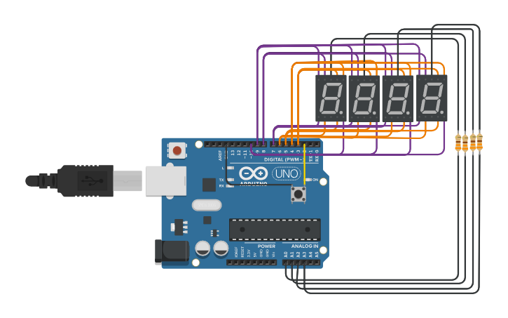
4 Digit 7-Segment Display. Take four 7-segment displays and solder them on a PCB in a side by side manner.
Interfacing Seven Segment Display On Tinkercad 4 Steps Instructables
This is currently being tested and will be released to the public site in a few weeks.
. Set up SevSeg library parmeters byte numDigits 4. Each of the seven LED is called a segment because when illuminated the segment forms part of a numerical digit to be displayed. Set to output pinMode echoPin INPUT.
Pin numbers for each digit byte segmentPins 23456789. We identified it from obedient source. Unfortunately the 7-segment display that is currently in Tinkercad is common-anode.
In the second example we will use tm1637 with arduino to create a simple temperature. This project aims to make a 4-digit 7-segment display SSD equivalent to the component 5641AS. 7 Segment Display Schematic - 17 images - 4 digit 7 segment shift register counter arduino implementation of four 7 segment led display multiplexing max7219 7 segments display example with arduino to the rails 7 segment display demo.
This design is for an anode display. The point is that in A B C. Any pin that has a resistor on it is one of the 4 digit pins otherwise they are the segment pins.
Showing number 0-9 on a Common Anode 7-segment LED display. In the first example we will look at the basic functions of the tm1637 display library and display some random numbers and letters. The FYQ-3641BH is a Chinese 4-digit 7-segment common-anode red LED Display.
Here are a number of highest rated 4 Digit 7 Segment pictures on internet. I have written the following code to multiplex a 4 digit 7 segment display with my Arduino Uno. We acknowledge this nice of 4 Digit 7 Segment graphic could possibly be the most trending subject as soon as we allocation it in google plus or facebook.
11 wires are used to connect the 4 Digit 7-Segment Display to the Arduino. Each of the seven LEDs is called a segment because when illuminated the segment forms part of a numerical digit both Decimal and Hex to be displayed. We will learn how to use the tm16374 digit 7 segment led display with arduino.
Take four BC548 NPN transistors connect each transistor emitter to each anode of 7 segment display. Tinkercad Projects The 7-segment display also written as seven segment display consists of seven LEDs hence its name arranged in a rectangular fashion as shown. Const uint8_t LedB 8.
We take on this nice of 4 Digit 7 Segment Display Arduino graphic could possibly be the most trending topic subsequently we ration it in google plus or facebook. Const uint8_t LedC 7. 4 Digit 7 Segment.
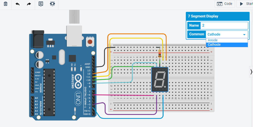
Pin Out 4 Digit 7 Segment Display. Common Cathode 7-Segment Display. Its submitted by organization in the best field.
A cathode or anode display can be used. Combine the 7 pins pin-a to pin-g and the dot pin of all the four displays. About Press Copyright Contact us Creators Advertise Developers Terms Privacy Policy Safety How YouTube works Test new features Press Copyright Contact us Creators.
The named digit here the 0 first digit turns off and the remaining ones. We identified it from trustworthy source. Heres the internal diagram of the 12-pin LED display with pin out information.
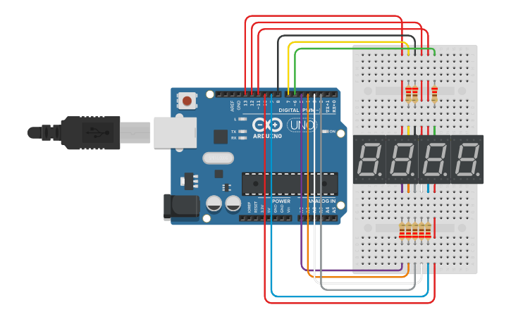
Now I have made the mistake so that when calling the showDigit function although the correct numbers are displayed but not on the mentioned digit from the parameters. Circuit design 2 Temp reading 2 4 digit 7 segment displays Tinkercad. Here is the Code.
Set to input. Number of digits on the display byte digitPins 13121110. To create the 4 Digit 7-Segment Display timer you will need the following.
I have modified the 7-segment to allow it to be configured as common-anode or common-cathode. The other 4 out of the 12 pins control each of the 4 digits on the display. The CD4511 is intended to drive common-cathode 7-segment displays.
Usually its the other way around but not today. 7-Segment LED Display consists of seven LED arranged in a rectangular fashion as shown. Here are a number of highest rated 4 Digit 7 Segment Display Arduino pictures on internet.
2 wires are used to connect the Push Button to the Arduino. Then to test it in TinkerCAD and compare it with the real-li. Circuit Diagram The 74HC595 IC uses the standard SPI interface and thus accepts three serial control signals from the external microcontroller Serial Data In Serial Clock and Latch Clock.
What we do in This code is called multiplexing I recommend you watch the video t understand it better. When it says theyre HIGH theyre off an when it says theyre LOW theyre on. Pins for each part of the 7 segment display.
The model used was 5641AS. Circuit design 2 Temp reading 2 4 digit 7 segment displays created by Banned_L GamePlay with Tinkercad. Circuit design Copy of 7-Segment 4-Digit LED Display created by Rachma Azis with Tinkercad ADSK Web Analytics Foundation Cross-Domain Solution Web Analytics Foundation.
A 4-digit 7-segment LED display has 12 pins. Its submitted by direction in the best field. There are 7 segments used to form any digit while one controls the decimal point.
Arduino pins connected to the 4511 const uint8_t LedA 5. In this circuit 4 position DIP switches are used. The display can be controlled in this tutorial.
4 Digit 7 Segment Display Clock Tinkercad
7 Segment 4 Digit Led Display Tinkercad
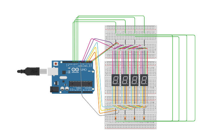
Multiplex 4 Digit 7 Segment Tinkercad
No comments for "4 Digit 7 Segment Display Tinkercad"
Post a Comment